|

Learning, Work and Entertainment
      |
| |

An X3D Browser for VR Immersive Simulation Based on Clusters of
Commodity Computers.
JINX is a fully distributed virtual environments browser, which has a
special support for commodity computer clusters and immersive
visualization devices. The presented mechanism intends to be fast and
easy to use to develop virtual reality applications based on the X3D
format, enabling great flexibility for displays and interaction
devices, allowing users to concentrate only on content creation. JINX
provides support for nodes synchronization and resources sharing, from
Framelock to Datalock. This paper describes the background of the
decisions made and the problems that had to be overcome.
Intro
Three-dimensional virtual experiences are important steps in many
fields of science and industry, and one of the reasons of their success
is the availability of commodity computers with powerful 3D resources.
Therefore commodity computer clusters are becoming a feasible solution
for immersive visualization systems, since they provide the necessary
hardware to support screens synchronization.
The goal of this paper is to present JINX, a tool that allows users to
develop distributed virtual reality applications, based on the recent
developments in commodity computers clusters. The application
development consists of either programming in graphical APIs, like
OpenGL routines or, the main focus, writing X3D files. At the moment we
support the X3D Interchange profile and we are almost finishing the
Interactive profile. Also part of the Immersive profile was already
done. JINX was created to be easy to understand and program. Although
this solution is focused on commodity clusters, JINX also supports
traditional graphical supercomputers, because those are widely
available in traditional virtual reality facilities.
The parameters for the physical and virtual environment can be set very
quickly. An XML file defines the configuration. XML was chosen because
it does not limit neither the semantics nor the tag set, it allows the
construction of richly structured documents that can be used over the
web, and it is open source. It is also possible to send other kind of
data, like images or sound through the network. This simple structure
is fully supported and easy to read and change, even in complex
situations.
The system is based on modules, therefore the user can increase special
support to other capabilities, for instance, visual and audio system
resources. This project is intended to be a public domain programming
library, running on different Linux distributions and also on IRIX.
This paper is organized as follows: Section 2 presents a background in
distributed systems, virtual reality and immersive systems, and also
some previous work conducted in this field. Section 3 presents the
communication system: from synchronization to data transfer. Section 4
regards the scene graph of X3D. Section 5 explains the modularity of
the system. Section 6 presents the navigation and interaction logic.
Section 7 explains how to develop an application. Finally section 8
presents some conclusion and future work.
Synchronization
The application presented in this paper allows the user to choose the
communication system between the processes. At this moment MPI and
TCP/IP sockets network streams are supported. All the information, like
the user position, direction and speed is packed and transmitted by
networking every frame, since this information is not too big. In a
dedicated fast-Ethernet connection it is possible to get a maximum
frame rate of about 60 f/s and in a gigabit-Ethernet of about 240 f/s.
We chose MPI because it is broadly supported and many network systems
support some sort of MPI distribution.
An important feature of the system is the Framelock and Datalock. In
the solution proposed, this is done mainly by a barrier function. The
Framelock blocks the graphical processes until all of them conclude
their own image rendering. When all of them finish their rendering, a
command that is issued at the same time in all graphical processes,
swaps the frame buffer. Figure 1 shows a system with two displays one
synchronized and one not synchronized. The Datalock is basically
necessary to guarantee the integrity of the information in the nodes
along the process and to avoid coherence problems.
 |
 |
 |
 |
| Figure 1 - Image with and
without Framelock and Datalock |
A suggested intermediate locking is the Timelock, because X3D is
animated and based on a specific time, therefore all computer nodes
receive a time update at each frame, based on the master clock, and it
is possible to predict the animation of the virtual objects, based on
this time.
Genlock is also an important resource for distributed environments. In
complex cluster-based immersive visual environments, many video signals
are necessary to show the images. The Genlock provides controls to
synchronize multiple screens, Genlock performs four main functions:
vertical, horizontal, frame, and color synchronization and it is
necessary in active stereo systems, as the active glasses let you see a
different image for each eye on each video refresh. JINX does not
provide Genlock, but some graphics cards have a connector for the
Genlock signal, which makes it very simple to synchronize the cards. If
the graphics card does not support it, another solution is necessary.
One of them is Softgenlock, which uses resources of a real time Linux
kernel that allows sending synchronization signals across the parallel
port.
Connection
The application developed can run in many processes, which are
responsible for different activities. Figure 2 shows how the messages
are transmitted across the system. This approach allows the use of
heterogeneous clusters or even different architectures for different
tasks. For instance the joystick could be connected to a node and the
sound card to another one. This allows the use of the cluster with
great efficiency.
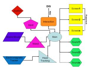 |
| Figure 2 – Network
Connection System Sample |
The main process is the one responsible for the communication with the
other processes, and for sending synchronization messages and merging
the data to a common repository, letting every node know about the
state of the system.
There are many processes responsible for input treatment. The input
devices supported are: keyboard, mouse, Labtec space mouse, any kind of
joystick, Ascension electromagnetic tracker and Intersense head
tracking devices. All the information from input devices is treated by
the input, wand or head tracking process, filtered, synchronized and
sent to the master process, and finally sent to the output processes,
like video and sound processes. If there are more than one input
devices, it is possible to rate all the device values.
Each input device works in a different way, returning information in
different styles. For instance, the tracker sends information in a
relative world position. This information has to be managed to fit in
the real world. Instead of having the processes reading the devices
directly, they can read the data generated by another application that
gets the hardware information, calculates the least squares formula,
converts the data to the real world coordinates and sends it in an XML
stream across the network. In this case the device could be in any
computer, outside the system. These messages transferred between the
processes should be managed so as not to overflow any other device. The
master node should send some messages of acknowledgment to the input
device processes to control the quantity of messages transmitted. In
the case of using MPI, it buffers the transmitted message, and if it
overflows it loses interactivity.
The output devices supported are video and sound. It is possible to use
video with the correct stereoscopic view, for many kinds of virtual
reality environments, like CAVEs, DisplayWall or Spherical system.
An important feature is the capability to correct the viewpoint of the
user, based on a head-tracking system. Usually it uses an
electromagnetic tracker for this. The rotation and movement of the eyes
should be informed to the computer, allowing it to redisplay the image
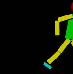
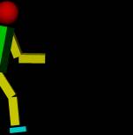
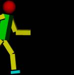
in a correct perspective. Figure 3 shows how the perspective frustum
transforms for an example viewpoint. For stereo the image is similar,
but there are two frustums with the source separated by the eye
distance.
The sound spacialization is very important; it radically helps the
feeling of immersion. For the immersion, sound sources points are
defined in the virtual space. Many speakers can be set around the
environment or the user can use some headphones. If the user is using
headphones, it is necessary to use some tracking system to determine
the user position and orientation in the environment. Otherwise each
sound connector in each cluster node could control one sound speaker.
The sound system is based on the Fmod library. It has the feature to
generate 3D sound spacialization, making the user aware of where the
sound is coming from.
Tasks distribution
The communication across the processes should be as highly efficient as
possible. JINX takes advantage of the SMP systems, that are common
nowadays, and high-speed network connections, defining a transparent
protocol for communication. Posix threads and MPI were chosen for each
respective communication. The processes are deployed to each node of
the cluster based on a shell script that internally uses the mpirun
command to control which computer will run the application.
SMP systems also use OpenMP for internal loops. Unfortunately it is
supported mainly in commercial compilers. The specified communication
protocol basically defines the following functions: Send(), Receive(),
Barrier(), Acknowledgment(), and some variations. Then based in the
dispatch script and the configuration file, showed in Code 1, the
program chooses the best way to start the application in each node,
which tasks it is responsible and how to communicate with other
processes. The dispatch script defines what each node will take care
of, like sound, video and input devices. And the configuration file
defines how each node works: like screen resolution or speaker’s
position. Sometimes one node could have more than one viewport, this is
a common case on Irix. In these architectures it is possible to open
many viewports in different graphic pipelines. |
<jinx>
<navigation DEF="Navigation" />
<computer hostname="sgi">
<device
DEF="FOB" dev="/dev/ttyd0" />
</computer>
<computer hostname="foo1">
<device
DEF="SpaceBall" dev="/dev/ttyS0" />
<render>
<wand
DEF="Wand" type="mouse" />
<window
name="front" pipe=":0.0">
<view
mode="stereo" InterocularDistance="0.007" />
<size
width="640" height="640" fullscreen="TRUE" />
<position
x="0" y="0" />
<screen
dir="0 0 -1" up="0 1 0" />
<frustum
left="-1.5" right="1.5" bottom="-1.5" top="1.5" depth="1.5" />
<center
x="0" y="0" z="0" />
<head
DEF="Head" pos="0 0 0" rot="0 1 0 0" />
<mask
url="http://foo/mask.png" />
</window>
</render>
</computer>
<computer hostname="foo2">
<device
DEF="Joy1" dev="/dev/js0" />
<sound>
<speaker
name="front1" channel="left" pos="2 2 0" />
<speaker
name="front2" channel="right" pos="-2 2 0" />
<speaker
name="headset" channel="headphone" />
</sound>
</computer>
<ROUTE fromNode='FOB'
fromField='position'
toNode='Head'
toField='position'/>
<ROUTE fromNode='FOB'
fromField='orientation'
toNode='Head'
toField='orientation'/>
<ROUTE fromNode='SpaceBall'
fromField='position'
toNode='Wand'
toField='position'/>
<ROUTE fromNode='SpaceBall'
fromField='orientation'
toNode='Wand'
toField='orientation'/>
<ROUTE fromNode='Joy1' fromField='move'
toNode='
Navigation ' toField='move'/>
<ROUTE fromNode='Joy1'
fromField='rotation'
toNode='Navigation'
toField='rotation'/>
</jinx>
|
|
| Code 1 – Example of configuration |
| |
As showed in Code 1 each computer configuration
is centralized in a common repository. It facilitates the management of
the system, allowing the composition of very complex systems. Aside
from the fact that the insertion of a new node in the cluster is
simple, all executable and configuration code can be read remotely. The
specification used in Code 1 was created to support the more common
virtual reality infrastructures, and it tries to follow the format of
X3D.
Scene graph
The library supports both an OpenGL routine
and an X3D code. The X3D system is based on a scene graph and it should
be controlled in a smart way. Because of the architecture of C++, it is
very simple to simulate each X3D node as an object. The X3D system has
some non-linear links. It means that one node connects with another one
in a different part of the tree. To solve this, a STL solution was used
to create a map that connects the nodes in any order. It also helps the
wand interface, the collision between the wand bean and the object is
calculated using a ray tracing algorithm that gets the X3D nodes
position very fast, making an accurate localization possible.
A XML parser is necessary to parse an X3D file. In this project we use
the public parser Xerces. The X3D structure has some points that should
be carefully managed, like the waste of memory. Some file lines in an
X3D object could have billions of points, represented as floating point
numbers. In this case a great quantity of memory is necessary, and this
should be dynamically allocated and freed.
Interaction and navigation
There are two control possibilities in a
virtual environment: the navigation system and the interaction system.
The navigation allows the user to walk, fly or execute other movements
inside a virtual world like to move to any viewpoint and to get closer
or farther from somewhere. Another possibility is the interaction with
the world. This is accomplished with a wand that lets the user point at
something and changes some parameter, like the position, or even the
color or the shape of an object.
The traditional input devices are the mouse and the keyboard, but these
two are not ideal for virtual environments. Usually the mouse works
only in 2D and the keyboard is not easy to carry around in a virtual
environment like a CAVE or Power Wall. But for simulation environments
in a single screen it is strongly recommended, and in this case it
should be supported. As many displays are supported, each one has to
support a keyboard and a mouse, and has to read and send information to
the master process so that the other drawing nodes are informed.
The positional electromagnetic trackers are the most popular input
devices for immersive environments. There are wired and wireless
models, but the wire usually is not a problem for small motion. The
tracker could deliver 6DOF, it is possible to locate the position and
the orientation the user’s head to change his/her viewpoint or to
change the wand position to detect and select a virtual object. It is
just important to remember that the viewpoint can be changed by any
movement in the virtual environment and also using the tracking system.
But these devices do not fit very well for simulation systems in small
areas. In this case the use of a space ball is a better idea. It fits
in the same space of a mouse, and it allows the same 6DOF of the
tracker.
These devices are usually connected by a RS232 or USB connector, and
sometimes these devices are not attached in the simulation computers.
In this case it is possible to connect this device in a specific
computer and send the information by a network stream, using a protocol
in XML specified by the library.
Development of an application
One of our first approaches to create 3D
content was to use a conversion tool that generates an OpenGL code from
some 3D format, but very soon we concluded that it was not a good way
to solve the application data conversion. Then we decided to read
directly the 3D file. As VRML is becoming obsolete for the technologies
available today, a new programming platform that is promising is the
X3D. It is a powerful system, platform independent and open. It is
quite possible that many companies start to use X3D for a unified 3D
format. There are some missing structures that could be important in
this format, but probably they will appear soon. The XML parser is used
to read the X3D files. OpenGL is used to render the X3D objects, and
the entire scene graph is implemented, following the structure of the
X3D model. This X3D file usually stays in a web site, and could be
accessed anywhere.
To write an application is quite simple. It is necessary to instance
the Engine class, and define the configuration file. Finally you
specify an X3D file or an OpenGL routine.
#include "engine.h"
int main(int argc, char* argv[]) {
Engine* engine = new
Engine(&argc,argv);
engine->Config("http://foo/render.xml");
engine->X3D("http://foo/exemplo.x3d");
//engine->OpenGL(&myDrawGLScene);
engine->run();
delete engine;
return(0);
}
|
|
| Code 2– Example of program |
In the Code 2 figure, you can see that the development of a simple
application is very easy. Actually, you can just create an interface
for this application and have a program that reads X3D files and
displays it in your virtual environment. In the case of using X3D, the
program first unpacks the file in a scene graph tree, and starts to
render it in each necessary node.
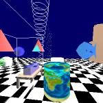
Results
Here, there are a few images produced by the
system. Some of them are in a CAVE and others are snapshots of screen
images.
 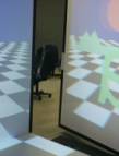  |
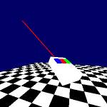
| Figure 6 – Demo application
in the CAVE and Monitor Wall |
Figure 6 shows a demo application that uses all the features already
implemented. It is possible to see the tracking system work for the 3D
wand. This virtual environment was the first one created, used to do
tests.
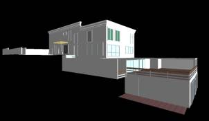

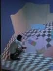
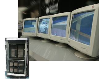 |
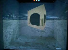
| Figure 7 – Snapshot of the
house model and linear monitor wall |
Figure 7 shows a house that was fully modeled using 3D Studio,
converted to VRML and then converted to X3D. This is a real house, and
has many special characteristics. The last image shows a monitor wall
presented at an important conference in Brazil, in this case was used 4
PC computers, each one driving one monitor
 |
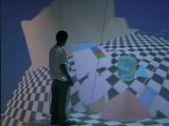
| Figure 8 – The Escher model |
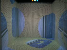
Figure 8 shows a simulation in the CAVE of an Escher drawing . This is
a famous drawing that makes some illusions using the perspective
feeling. In this application we have 6 PC computers and a SGI computer
to produce this simulation. The tracking system, a flock of birds, is
attached at the SGI that sends a XML stream with the coordinates to the
PC master computers. This computer is responsible to manage all other
computers and synthesize the audio. The remaining 5 computers are each
one responsible to render the image for each wall.
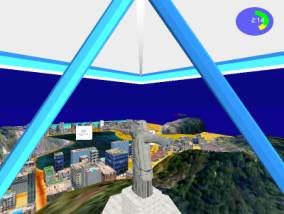 |
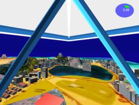
| Figure 9 – Snapshot of
hang-gliding over Rio de Janeiro |
Figure 9 shows a hang-gliding tour over Rio de Janeiro. It is possible
to see many important places, like Corcovado and Sugar Loaf. This
example has some sounds in Maracanã, the biggest soccer stadium,
and Sambódromo, the carnival parade avenue. Besides the
environment plays the song Girls from Ipanema. This example was created
with Alias Wavefront Maya and converted to VRML/X3D.
contact: lsoares@lsi.usp.br
|
| |
   |
|
 |