Making Of:
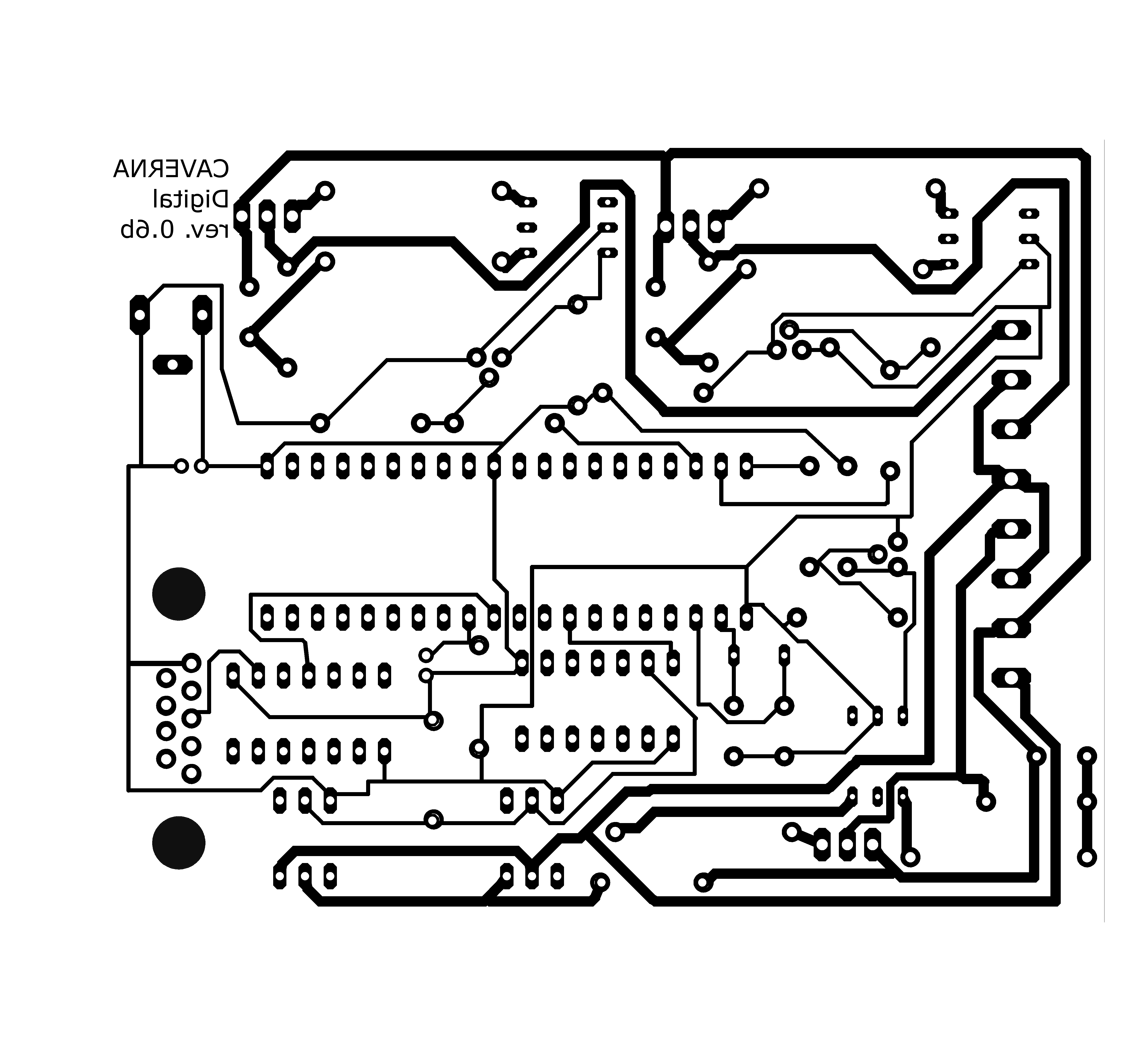
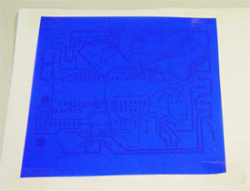
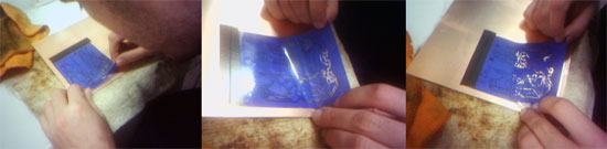
1.Printing the board schema
Print the schema in a peace of paper and put the easypeal over the printed scheme. Don’t use the easypeal directly in the printer. It will cause paper jam. Put some tape to hold the easypeal (just around the corners). If you put tape in all side the tape can shrink inside the printer and deform the shape of the paper and compromise the printing. You should use the rough side of the easypeal to receive the print. Use the best print quality available.
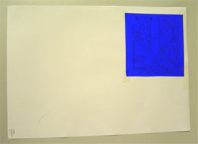 
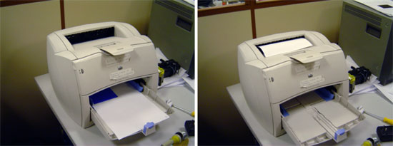
In the printer, take care to print in the right side.
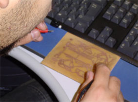
2. Applying the printed schema over the copper board
You must first remove the grease of the board with a straw steel. Your movements must be in the same direction, it is not recommended to do circular movements.
Put the easypeal over the copper board, with the printed part to the bottom. You can put some tape to easily move the paper to the right position after you warm the copper board. It is recommended that you have some peace of cloth under the board, otherwise you can burn your table.
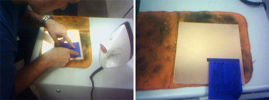
Heat the copper board for about 1 minute.
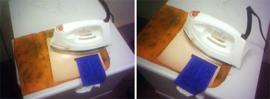
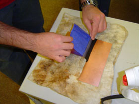
Now move the easypeal over the board, you can use a ruler to help you, to put it in a flat area.
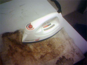
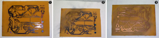
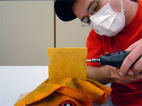
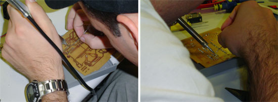
Put a peace of cloth over the copper board and the iron over this. Make sure you cover all the board or some area. You can rotate as you leave the iron heating the board. We achieved a maximum performance leaving the iron in 4 steps of 12 minutes, rotating 90o degrees over the board.
To get a more fast and strong transfer of the printed board schema, it is recommended to cool down the board in water. You can leave there for about 4 minutes. After remove and dry the board with a cloth.
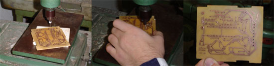
Remove the paper carefully. We used a small knife to help remove it.
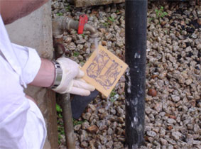
Cut the board to get just the tracks, and reuse the other area of the board.
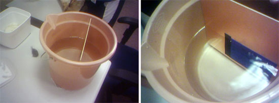
Now you have to use Percloreto de Ferro to remove the copper that was not painted, it can take some time. It is possible to find ready solutions in the market. Drench the board until you just see the tracks, but dont leave it too much, because it can start to remove the copper under the ink.
Probably this processes will fail in some places, in this case you can use a retroprojetor pen to complete some path that was not complete. You can use magnifying lenses to help you find the problems.
After this, clean the board with water.
Remove the ink with straw steel. Again, your movements must be in the same direction.
Test the board to see if there are problems. You can use a voltmeter.
Test the board in the box that you are going to put the board, and cut the areas necessary to fit the board.
Drill the holes in the board, in our case we used a 0.9mm drill
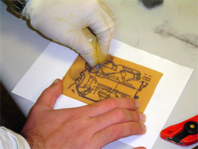
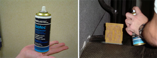
Apply varnish.
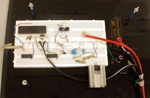
Put the components and weld
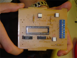
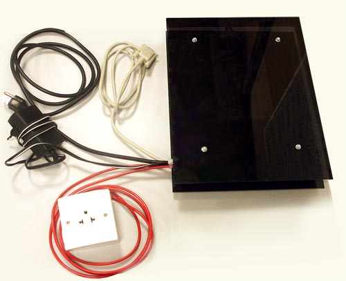
The box must be big enough to accommodate the board. In our case we have 3 power outputs.
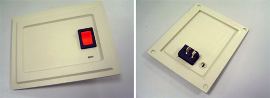
Put a switch to turn on and off the system. You can use also a LED to inform the status.
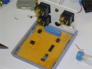
The cooler can be used to cold the box inside, but it is not a requirement.
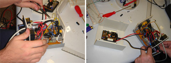
Finally connect all components, in our case the AC adapter is over our board inside the box.
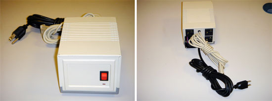
Ready, this is the fan control box that we developed,
we tested it 6 consecutive days, 8 hours per day, and worked perfect.
|